

Weather Satellite Antenna
There are various weather satellites in orbit which periodically transmit information and images. The communication protocols and bands are publically available for many of them, meaning amateurs can receive these transmissions and extract the data.
Foreword
The idea for this project came about after seeing this video. The idea seemed very cool and accessible to beginners to RF and antennae. My plan is to use the design from the video to get a working model, and then make improvements to it as my knowledge of the subject grows.
More information can be found about the METEOR satellites on an archived page from the NOAA. I hope to target these satellites as well as the NOAA ones mentioned in the video. Information on building the antenna from the video can be found here.
Antenna Design
As mentioned in the video, the antenna design is going to be that of a double cross antenna. It is simple to build, and according to the linked article, forgiving to design variations. The NOAA satellites, as well as many others, utilize a right-hand circular polarized signal. Therefore in order to get the best possible reception, an antenna designed for RHCP waves is necessary. Additionally, as the article states, the radiation pattern should be stronger on the horizons and weaker vertically, because the satellite signal will be weaker on the horizon as it passed through more of the atmosphere.
The design takes two sets of dipoles, running cross to each other, a quarter wavelength apart. This produces a good omnidirectional radiation pattern but has a null along the X axis. To correct this, a second pair is used at a 90 degree physical angle to the first. If this pair is fed 90 electrical degrees later than the first, the radiation pattern is similar to the one described above.
The height of the antenna is also important, and the reference design uses a height of 2 wavelengths. However, this is quite high and difficult to mount, so I will use a height of 1 wavelength and increase this if needed.
The antenna design used here has a center frequency of 137 MHz, which is a wavelength of 218.8 cm.
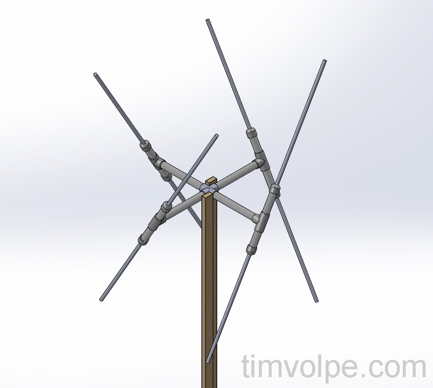 The Double Cross Dipole Antenna Design
The frame is constructed of wood, and the antenna hardware mount is constructed of PVC. Each pair of dipoles is separated by a distance of 54.7 cm, a quarter wavelength. The angle of the dipoles is specified as a 30 degree tilt.
The antenna material used will be aluminum instead of copper. This is because copper oxidizes when exposed to the elements. The aluminum rods will each be 54.7 cm in length, with 8 in total. The dipoles are half-wave dipoles, so the combined length of each totals a half wavelength.
The PCV fittings allow the dipoles to be rotated and adjusted as needed. The fixed joints will be sealed with PVC cement to prevent water ingress. Coaxial cable will run from each dipole to the center, where they will be joined per the wiring specified by the reference design. Each pair of 50 Ohm coax will be wired in series, then the two pairs will be wired in parallel to maintain a 50 Ohm line.
Constructing the Antenna
Construction of the antenna was relatively simple. 4 foot aluminum rods were cut and used as the dipoles. Inside the PVC tee joints, each end of the dipole is joined with a piece of nylon spacer. There is a small plastic bead placed inside the spacer to keep the dipoles from contacting and shorting out. Vinyl tube was slid on the rest of the dipole within the PVC to hold it in place against each cap. The coax is connected to each piece by forcing the wire under the nylon spacer and using conductive grease. This way the entire setup can be dissembled or modified if needed.
Crimp-on female SMA connectors are used to connect each dipole, with male connectors soldered to the wires wrapped around the dipoles. Each dipole was then connected in the manner mentioned above, with two in series and then the series pairs in parallel. Finally, the coax runs down a patch cord to the RTL-SDR.
Software
Crimp-on female SMA connectors are used to connect each dipole, with male connectors soldered to the wires wrapped around the dipoles. Each dipole was then connected in the manner mentioned above, with two in series and then the series pairs in parallel. Finally, the coax runs down a patch cord to the RTL-SDR.
For the old NOAA satellites such as NOAA 18, WXtoImg is used to convert the .wav file to a visible image. It is very simple to use and works well.
For METEOR satellites, the process is more complicated and requires extra software and plugins, which can be found in the video linked above.
To track the position of the satellites, there are numerous websites and programs, but I chose to use Orbitron for the simple interface and because it is highly regarded in the community.
Receiving Images
To receive an image, first one must wait for the satellite to pass overhead. This happens a few times a day, but many of these passes remain close to the horizon or are not in range for long. When a satellite comes into range, a very distinct signal will appear that sounds like a high-pitched tone with a metronome sound in the background. When this sound is very clear with little static, the image will be clear. If there is static, the image quality is significantly reduced. Sometimes it can be difficult to get a clear signal.
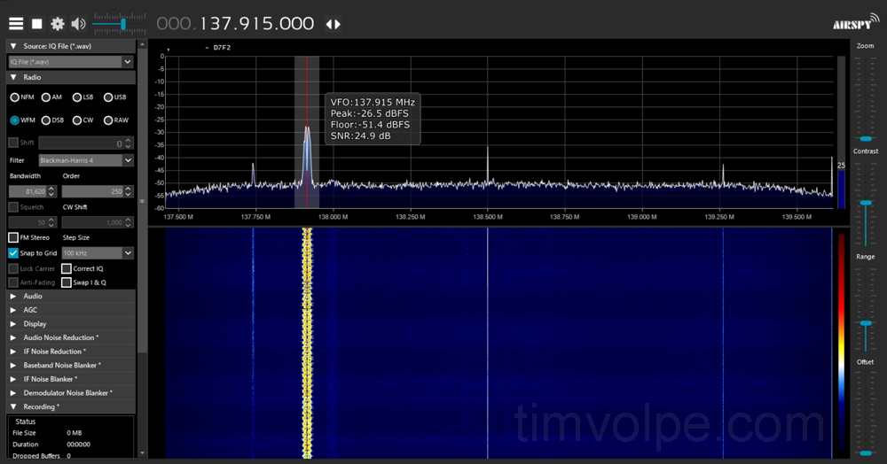 The Signal seen in SDRsharp
I was able to get a good clear pass at night and download a fairly high quality image. Unfortunately because it was taken at night only the clouds are clearly visible.
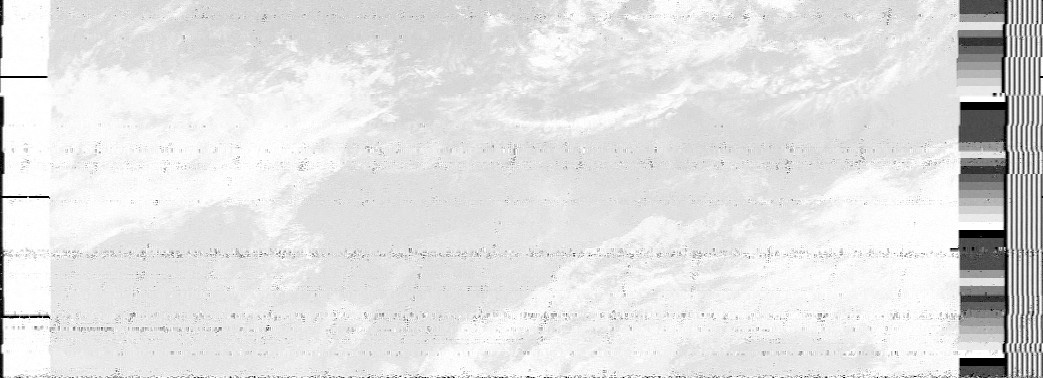 Image from NOAA 18 at Night
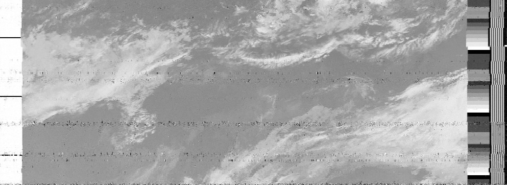 Infrared Image from NOAA 18 at Night